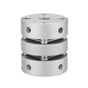
GLJ Shaft Coupling Diaphragm Coupling Aluminum Flexible Shaft Coupling Marine
Products Introduction
Couplings are also called couplings. Most of the commonly used couplings have been standardized or standardized. Generally, it is only necessary to correctly select the type of the coupling and determine the type and size of the coupling. When necessary, the load capacity can be checked and calculated for its vulnerable weak links; when the rotation speed is high, the centrifugal force of the outer edge and the deformation of the elastic element should be checked, and the balance check should be carried out.
A mechanical component used to firmly connect the driving shaft and the driven shaft in different mechanisms to rotate together and transmit motion and torque. Sometimes it is also used to connect shafts and other parts (such as gears, pulleys, etc.). It is often composed of two halves, which are respectively connected by keys or tight fittings, and are fastened at the ends of the two shafts, and then the two halves are connected in some way. The coupling can also compensate for the offset (including axial offset, radial offset, angular offset or comprehensive offset) between the two shafts due to inaccurate manufacturing and installation, deformation during operation or thermal expansion, etc. ; and shock mitigation and vibration absorption.
General coupling function: When the shaft and the shaft are to be connected to transmit power, a pulley or gear is generally used for connection, but if the two shafts are required to be in a straight line and required to rotate at a constant speed, a coupling must be used to connect. However, due to the increase of precision, the thermal expansion of the shaft or the bending of the shaft during operation, the concentricity between the two shafts will change. Therefore, the flexible coupling can be used as a bridge to maintain the power transmission between the two shafts and absorb the two shafts. Radial, angular and axial deviation between shafts, thereby prolonging the life of the machine and improving the quality of the machine.
Products Parameters

| model parameter | common bore diameter d1,d2 | ΦD | L | LF | LP | d3 | S | F | M | tightening screw torque
(N.M) |
| GLJ-19x27 | 3,4,5,6,6.35,7,8,9,9.525,10 | 19 | 27 | 9.1 | 5.2 | 9 | 1.8 | 4.25 | M3 | 0.7 |
| GLJ-26x32 | 4,5,6,6.35,7,8,9,9.525,10,11,12,12.7 | 26 | 32 | 10.7 | 5.4 | 12.5 | 2.6 | 4.5 | M4 | 1.7 |
| GLJ-32x41 | 6,6.35,7,8,9,9.525,10,11,12,12.7,13,14,15 | 32 | 41 | 12.75 | 8.5 | 16 | 3.5 | 6.12 | M4 | 1.7 |
| GLJ-39x47 | 6,6.35,7,8,9,9.525,10,11,12,12.7,13,14,15,16 | 39 | 47 | 15 | 8 | 19.3 | 4.5 | 6.62 | M5 | 4 |
| GLJ-44x53 | 8,9,9.525,10,11,12,12.7,14,15,16,17,18,19,20 | 44 | 53 | 18.25 | 7.5 | 22.5 | 4.5 | 8.12 | M6 | 8.4 |
| GLJ-56x64 | 10,11,12,12.7,13,14,15,16,17,18,19,20,22,24,25,28, 30,32 | 56 | 64 | 19.75 | 13.5 | 32.5 | 5.5 | 6.4 | M6 | 8.4 |
| GLJ-68x75 | 12,14,15,16,17,18,19,20,22,24,25,28,30,32,35,38 | 68 | 75 | 23.35 | 15.7 | 45.5 | 6.3 | 7.7 | M8 | 10.5 |
| Anodizing treatment | Rated torque
(N.M)* | allowable eccentricity
(mm)* | allowable deflection angle
(°)* | allowable axial deviation
(mm)* | maximum speed
rpm | static torsional stiffness
(N.M/rad) | moment of inertia
(Kg.M2) | Material of shaft sleeve | Material of shrapnel | surface treatment | weight
(g) |
| GLJ-19x27 | 1 | 0.12 | 1.5 | ±0.18 | 10000 | 170 | 8.8x10⁻⁷ | High strength aluminum alloy | S U S 3 0 4 Spring steel | Anodizing treatment | 13 |
| GLJ-26x32 | 1.5 | 0.15 | 1.5 | ±0.3 | 10000 | 820 | 2.8x10⁻⁶ | 29 |
| GLJ-32x41 | 2 | 0.17 | 1.5 | ±0.36 | 10000 | 1750 | 1.8x10⁻⁶ | 60 |
| GLJ-39x47 | 6 | 0.22 | 1.5 | ±0.45 | 10000 | 2850 | 2.7x10⁻⁵ | 101 |
| GLJ-44x53 | 9 | 0.22 | 1.5 | ±0.54 | 10000 | 3300 | 4.2x10⁻⁵ | 190 |
| GLJ-56x64 | 25 | 0.27 | 1.5 | ±0.72 | 10000 | 9480 | 1.6x10⁻⁴ | 318 |
| GLJ-68x75 | 60 | 0.32 | 1.5 | ±0.8 | 9000 | 19000 | 2.0x10⁻⁴ | 492
|