Ask Latest Price
Verified Supplier
4 Years

Changzhou Tianniu Transmission Equipment Co., Ltd
Changzhou TIANNIU Transmission Equipment Co., Ltd is a professional one way clutch bearing supplier, the primary products are micro electromagnetic clutch, torque limiter coupling, sliding shaft


Add to Cart
Products Introduction
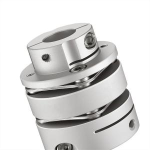
Diaphragm coupling generally refers to a set of diaphragm couplings equipped with two sets of diaphragms, which have the advantages of high mechanical strength, large bearing capacity, quality, etc. It is easy to install and has good reliability, because it has an intermediate shaft. , Its relative displacement compensation is very good, and the diaphragm coupling is suitable for medium, high speed and large torque shafting transmission. As well as the shafting transmission with little change in the load of various mechanical devices, it is extremely versatile. Therefore, the diaphragm is a wearing part corresponding to the coupling itself. Generally, the factory needs to prepare several sets of coupling diaphragms.
Diaphragm coupling has obvious damping effect, no noise, no wear, long life, suitable for working in high temperature (-80+300) and harsh environment, moving in the case of shock and vibration, high transmission efficiency, can be up to 99.86%. It is especially suitable for medium and high-speed high-power transmission, with simple structure, light weight, small volume, and convenient assembly and disassembly. It can be assembled and disassembled without moving the machine, without lubrication, and can accurately transmit the rotation speed, with no slip and fast rotation.
>High torque rigidity, can accurately control the rotation of the shaft, can carry out high-precision control
>Designed for servo and stepping motor
>No gap between the shaft and sleeve connection, general for positive and negative rotation
>Low inertia, suitable for high speed operation
>The diaphragm is made of spring steel with excellent fatigue resistance
>Fastening method of clamping screw
Products Parameters

| model parameter | common bore diameter d1 | common bore diameter d2 | D | ΦN | L | LF1 | LF | S | LP | d3 | M | tightening screw torque (N.M) | ||
| smallest | maximum | smallest | maximum | |||||||||||
| GLTS-34x42.9 | 5 | 12 | 5 | 15 | 34 | 21.6 | 42.9 | 12.15 | 14.25 | 3.5 | 9.5 | Φ16 | M3 | 1.5 |
| GLTS-39x50.2 | 6 | 15 | 6 | 19 | 39 | 25 | 50.2 | 15.15 | 14.9 | 4.5 | 11.15 | Φ19 | M4 | 2.5 |
| GLTS-44x50.2 | 6 | 18 | 6 | 22 | 44 | 29.6 | 50.2 | 15.15 | 14.9 | 4.5 | 11.15 | Φ22.5 | M4 | 2.5 |
| GLTS-56x64.1 | 8 | 24 | 8 | 32 | 56 | 38 | 64.1 | 19.90 | 19.75 | 5.5 | 13.45 | Φ32.5 | M5 | 7 |
| GLTS-68x75.6 | 10 | 30 | 10 | 38 | 68 | 46 | 75.6 | 24 | 23.35 | 6.3 | 15.65 | Φ38.5 | M6 | 12 |
| GLTS-82x98.1 | 16 | 38 | 16 | 45 | 82 | 56 | 98.1 | 30.15 | 30 | 8 | 21.95 | Φ45 | M8 | 20 |
| model parameter | Rated torque (N.M)* | allowable eccentricity (mm)* | allowable deflection angle (°)* | allowable axial deviation (mm)* | maximum speed rpm | static torsional stiffness (N.M/rad) | moment of inertia (Kg.M2) | Material of shaft sleeve | Material of shrapnel | surface treatment | weight (g) |
| GLTS-34x42.9 | 3 | 0.02 | 1 | ±0.20 | 10000 | 2000 | 6.01x10⁻⁵ | High strength aluminum alloy | S U S 3 0 4 Spring steel | Anodizing treatment | 57 |
| GLTS-39x50.2 | 6 | 0.02 | 1 | ±0.25 | 10000 | 4500 | 1.49x10⁻⁵ | 103 | |||
| GLTS-44x50.2 | 9 | 0.02 | 1 | ±0.30 | 10000 | 5200 | 2.25x10⁻⁵ | 124 | |||
| GLTS-56x64.1 | 25 | 0.02 | 1 | ±0.40 | 10000 | 11000 | 7.23x10⁻⁵ | 269 | |||
| GLTS-68x75.6 | 60 | 0.02 | 1 | ±0.45 | 10000 | 19000 | 2.02x10⁻⁴ | 471 | |||
| GLTS-82x98.1 | 100 | 0.02 | 1 | ±0.55 | 10000 | 22000 | 5.95x10⁻⁴ | 375 |